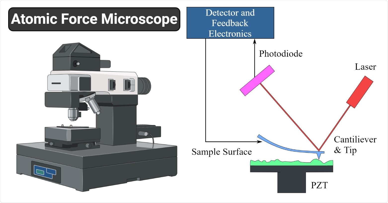
Atomic force microscopy (AFM) brought the atomic scale imaging resolution of scanning tunnelling microscopy, a technique that won the Nobel Prize in Physics, to non-conducting surfaces. However, imitations remain when trying to use the technique at its most sensitive with photosensitive samples in liquids.

Image Credit: https://microbenotes.com/atomic-force-microscope-afm/
Now researchers at Kanazawa University show how to overcome these constraints, by driving a cantilever a few micrometres in size at megahertz frequencies with stability and control in liquid and without potentially exposing the sample to light.
Atomic force microscopes monitor the forces at play between a surface and a tip attached to a cantilever to extract information about the surface topography and composition. By oscillating the cantilever over the surface instead of dragging it the strength of interactions with the cantilever and tip can be inferred from changes in the oscillation amplitude or resonant frequency without damaging the surface.
Usually a piezo actuator generates an acoustic wave that drives the cantilever to oscillate at its resonance frequency. However, this approach is prone to spurious contributions to the resonance from the components of the device linking the actuator to the cantilever. The impact of these effects is greater for the most sensitive cantilevers, which are small and have high megahertz resonance frequencies.
Alternatives are photothermal, electrostatic or electrostrictive cantilever excitation, but if the material under study is photosensitive or kept in an electrochemically active liquid, these too have drawbacks. Instead Takeshi Fukuma and colleagues at Kanazawa University followed up with a magnetic excitation approach.
They investigated how to implement their approach with three makes of cantilever, which they customized by adding a magnetic bead decorated with a carbon nanoscale tip. They then applied an alternating magnetic field by feeding an a.c. current into a tiny solenoid made from a 0.2 mm diameter wire wound around a 3 mm diameter cylinder.
Although other groups have previously demonstrated dynamic AFM driven by magnetic excitation, the approach once again runs into problems for small cantilevers. The feedback loop to handle the circuit latency and compensate for the frequency-dependent impedance so that the device covers a wide frequency bandwidth does not work so well at high frequencies.
Instead, the researchers designed an open loop differential circuit that feeds in a complex coil voltage proportional to the frequency and input voltage.
To demonstrate the applicability of their approach they measured cantilever resonance curves and the atomic scale topography of a mica surface in phosphate buffered saline solution with various customized cantilevers including those with a megahertz-order resonance frequency.
Atomic force microscopy
The first image using AFM was reported by Gerd Binnig, Calvin Quate and Christoph Gerber in 1986, five years after the scanning tunnelling microscope. The technique is capable of atomic scale resolution and generates images by measuring the sum strength of a number of forces at play between tip and sample, including van der Waals and electrostatic.
AFM uses a cantilever with a tiny tip attached at the end. For static AFM the tip is dragged over the surface and the cantilever deflection is measured or, the cantilever height is adjusted to maintain a constant deflection.
In dynamic AFM, where the cantilever oscillates at its resonance frequency and taps the surface with the tip, contact between the tip and surface is causing less damage to the sample. It is capable of high sensitivity imaging without making contact with the surface at all in non-contact mode, by monitoring the impact of interactions with the surface on the amplitude and frequency of the cantilever oscillations.
Besides piezo actuated and photothermal cantilever excitation electrostatic and electrostrictive interactions can be used by applying a bias voltage between tip and surface or both sides of a cantilever. However, in many of the liquids used to house samples, this can cause uncontrolled chemical reactions.
Closed loop versus open loop with differentiation circuits
When using magnetic fields to excite oscillations in the cantilever, the circuit supplying current to the solenoid coil needs to maintain a constant current amplitude.
However, the impedance of the circuit increases with frequency, so that a higher voltage signal is needed to maintain a constant current amplitude. This is usually achieved with a feedback loop, which converts the coil current to a voltage and compares it with the input voltage. However, this feedback loop becomes unstable at megahertz frequencies.
In the open-loop circuit used instead, the input voltage is fed into a differentiation circuit that returns a complex coil voltage that is proportional to the input voltage and the frequency (Vcoil = iωVin, where Vcoil is the coil voltage, Vin is the input voltage and ω is the frequency.)
This way the coil voltage automatically scales with the frequency, compensating for the frequency-dependent impedance changes.